Posts tagged Engineering

Penrose Market Fly Away CAD
For the Penrose Market last week we had to create a complete studio in a Rack called a Fly Away. We had to create this Fly Away because the studio facilities at Ravensbourne were in use for another shoot on the same day.

This Fly Away was created using any available kit that we found on Level 9, then using the time in our 208 and 204 lectures to design and build the system with the help of James Uren and the rest of the BET Pathway. After an initial brain storm and specification we came up with a simple system that consisted of:
- 7 SD Cameras
- 1 VT Deck
- 1 16 Channel Vision Mixer
- 1 16×1 Router
- CTP and Jack Field
- 3 Digital DA’s – 1 Analogue DA in the Fly Away
- 8 Digital DA’s – 4 Digital to Analogue Converters in the Monitor Stack
- 10 Monitors
- 1 Large Engineering Monitor
- 1 Test Pattern Genorator
- 2 Wave Form Monitors
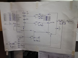
The initial brainstorm and scribbled drawing was then drawn up, neatly, onto a large A1 sheet of paper, along with a Cable Schedule and CTP / Jack Field layouts. This large Drawing was then attached to the side of the rack and used as a reference throughout the rest of the project.
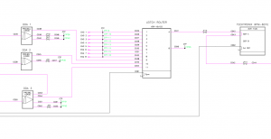
 After the project was completed on Tuesday (22/11/2011) we were required as part of our Hardware Systems unit (204) to draw up a full CAD in AutoCad based on the same layers and components that were used to create the CAD’s for the main system in Ravensbourne. This exercise was designed to teach us how to use CAD to create Technical Drawings as well as be confident in reading and updating existing drawings. A screen shot of mine can be found on the right, with a PDF copy of the final cad available for download below.
The technical drawing we had to create was in fact two drawings of two separate systems which interacted closely with each other. The first was the main Fly Away, which was a single rack with all the processing and routing required, and the second was of the Monitor Stack which was required to make the Rack work. This is a major problem with the system as it require one part to work to make the rest work, whilst also doubling the amount of video connections in and out of the rack. However these problems were only noticed after the initial and were not a problem in this project as the monitor stack and rack were being built side-by-side at the same time.
Having so many connection to and from the rack also opened up another problem, which could simply be caused by confusion during the connection of the rack to the video sources and the monitor stack. This confusion could lead to video being sent the wrong way into the system, which could cause damage to equipment, or for example a Camera could be fed into one of the ENG inputs, thus it would appear to work fine on the router but it would have completely bypassed the monitor stack and more importantly the Vision Mixer.
Above I talked about just a few of the problems with last weeks Fly Away, in time I may look into re-drawing the Technical Drawing to alleviate some of the faults mentioned, and when I have re-drawn a new version of the system I will post a comparison between the two.
Download an A1 PDF of my Technical Drawing Here.
Download a PDF copy of my Cable Schedule Here.
LECTURE: IPP
0This IPP lecture was a bit different than the others as it was with James Uren, one of our Broadcast Tech course Leaders. This made this session much more interesting and much more relevant to our corse and how the principles, we have been taught in the other IPP sessions, are used in a number of Broadcast Engineering environments.