Penrose Market Fly Away
 BTC204 CAD Reference Signals and Router Diagram – Scott Campbell 30/11/11 – Router:Sync diagram Penrose Market 2011
This term we were asked to broadcast an event at Ravensbourne onto the internet. Normally this would mean that we would book out the television studio and use the all of the main infrastructure of Ravensbourne, however due to timetabling errors we were left with no studio and basically no infrastructure, so we ended up constructing a fly away studio out of the bits of kit in the engineering department. This involved several days of planning and working out how we could to use the infrastructure that we did have access to to get the best out of a dire situation. The first problem that we had was not having enough tie lines on the 9th floor to accommodate having 10 cameras, so we ended up only using 7 cameras.
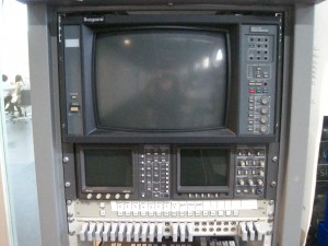
My CAD drawings are of the main router that was in the fly away and the sync pulse reference signals that are used to time all the equipment. The main black and burst signal came from the University’s infrastructure, we just routed it to a BNC socket on the 9th floor and used a distribution amplifier (DA) to copy the signal several times and send it down BNC’s to each device.
The main router that we used was a Leitch 16 x 1 which actually has 16 inputs and 2 outputs.